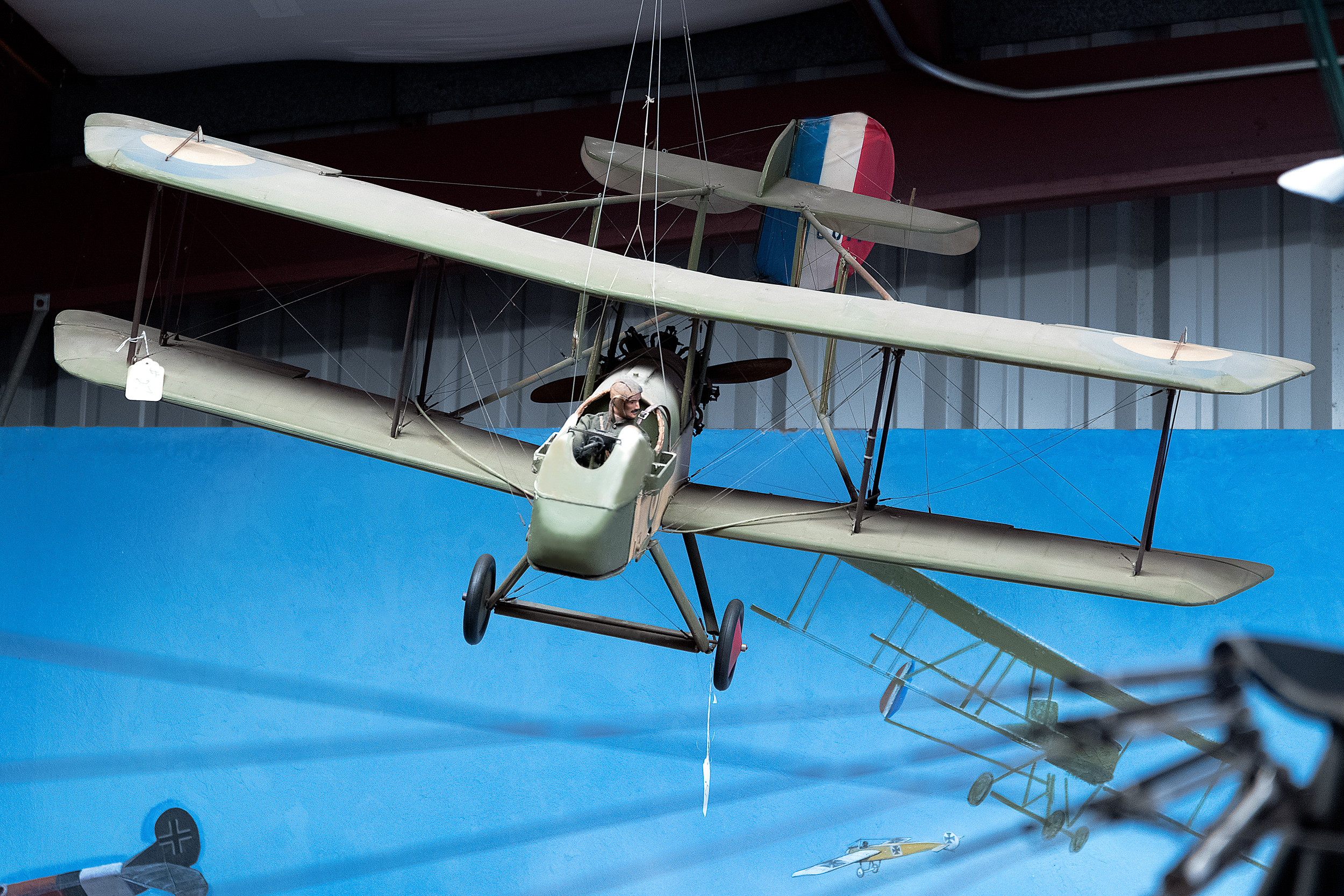
This model aircraft represents the Airco DH.2 that was a single-seat biplane “pusher” aircraft which operated as a fighter during the First World War. It was the second pusher design by Geoffrey de Havilland for Airco, based on his earlier DH.I two-seater. de Havilland designed the aircraft, but it was built by Airco. 453 of these aircraft were manufactured.
Early air combat over the Western Front indicated the need for a single-seat fighter with forward-firing armament. As no means of firing forward through the propeller of a tractor airplane was available to the British, Geoffrey de Havilland designed the DH.2 as a smaller, single-seat development of the earlier two-seat DH.I pusher design. The DH.2 first flew in July, 1915.
The DH.2 was armed with a single 7.7 mm Lewis gun which could be positioned in any one of three positions on its mounting. Once pilots learned the best method of using this equipment, they placed the gun in a fixed forward-facing position and merely aimed the aircraft rather than the gun.
The majority of DH.2’s were fitted with 100 HP Gnome Monosoupape rotary engines, but later models used the 110 HP Le Rhone 9J.
After arriving at the Front, the DH.2 proved to be more than a match for the Fokker Eindecker’s used by the Germans. The airplane had sensitive controls and at a time when service training for pilots in the military was very poor initially there was a high accident rate, which resulted in the airplane being given the name of “The Spinning Incinerator.” But as pilots built up time in the aircraft it was recognized as very maneuverable and relatively easy to fly. When the more powerful German tractor airplanes appeared in September, 1916, the DH.2 was outclassed.
Crew: One Pilot Takeoff Weight: 1441 pounds Wingspan: 28 feet 3 inches Maximum Speed: 93 mph Length: 25 feet 2 1/2 inches Source: en.wikipedia.org
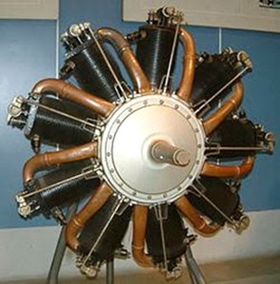 About the Airco DH.2 Rotary Aircraft Engine
The rotary engine was an early type of internal-combustion engine, usually designed with an odd number of cylinders per row in a radial configuration, in which the crankshaft remained stationary in operation, with the entire crankcase and its attached cylinders rotating around it as a unit. Its main application was in aviation, although it also saw use before its primary aviation role in a few motorcycles and automobiles. This type of engine was widely used as an alternative to conventional inline engines (straight or V) during World War I and the years immediately preceding that conflict. It has been described as a very efficient solution to the problems of power output, weight, and reliability. When viewing the various World War I aircraft models in the museum you will discover that a large percentage of these early aircraft were powered by rotary engines. Although rotary engines physically look a whole lot like radial engines, they are actually in a separate classification all by themselves.
By the early 1920’s, however, the inherent limitations of this type of engine had rendered it obsolete, with the power output increasingly going into overcoming the air-resistance (drag) of the spinning engine itself. The rotating mass of the engine also caused significant gyroscopic precession: depending upon the type of aircraft, this produced stability and control problems, especially for inexperienced pilots. Another factor in the demise of the rotary was the fundamentally inefficient total-loss oiling system, caused by the need to aspirate the fuel/air mixture through the hollow crankshaft and crankcase along with the lubricating medium, as in a two-stroke engine. In most common applications, the crankshaft was fixed solidly to the airframe, and the propeller was bolted to the front of the crankcase. There were three key factors that contributed to the success at the time:
–1. Smooth running – rotaries delivered power very smoothly (relative to the engine mounting point) there are no reciprocating parts, and the relatively large rotating mass of the crankcase and cylinders (as a unit) acted as a flywheel.
–2. Weight advantage – many conventional engines had to have heavy flywheels added to smooth out the power impulses and reduce vibration. Rotary engines gained a substantial power-to-weight ratio advantage by having no need for an added flywheel.
–3. Improved cooling – when the engine was running the rotating crankcase/cylinder assembly created its own fast-moving cooling airflow, even with the aircraft at rest. It is often asserted that rotary engines had no carburetor and hence power could only be reduced by intermittently cutting the ignition using a “blip” switch. This was literally true only of the Monosoupapetpe engine, which took the air supply in through the exhaust valve, and so could not be controlled via the crankcase inlet. Most rotaries, however, had normal inlet valves, so that the fuel and lubricating oil was taken into the cylinders already mixed with air – as in a normal four-stroke engine.
Although a conventional carburetor, with the ability to keep the fuel/air ratio constant over a range of throttle settings, was precluded by the spinning crankcase; it was possible to adjust the air supply through a separate flap valve or “bloctube.” The pilot had to set the throttle to the desired setting and then adjust the fuel/air mixture using a separate lever that controlled the air supply.
Source: en.wikipedia.org